|
|
hace 1 año | |
|---|---|---|
| .. | ||
| extra | hace 1 año | |
| gerbers | hace 5 años | |
| pics | hace 1 año | |
| schematics | hace 1 año | |
| CHANGELOG.md | hace 1 año | |
| DuPal_DIP.kicad_pcb | hace 5 años | |
| DuPal_DIP.kicad_prl | hace 1 año | |
| DuPal_DIP.kicad_pro | hace 1 año | |
| DuPal_DIP.kicad_sch | hace 1 año | |
| DuPal_DIP.sch | hace 5 años | |
| README.md | hace 1 año | |
| fp-info-cache | hace 1 año | |
| fp-lib-table | hace 5 años | |
| sym-lib-table | hace 1 año | |
README.md
DuPAL board
DISCLAIMER
Any use of this project is under your own responsibility. You will be responsible of checking the correct construction and functionality of your board and the compatiblity of the chips You will insert into it. By using this project You will agree that I cannot be held responsible if it will destroy any of your devices, damage your computer, burn down your house or whatever.
Do NOT come to me for hand-holding using this. It is NOT a plug-and-play tool, and it is something I created for my own use and I released in case someone might have an use for it.
Introduction
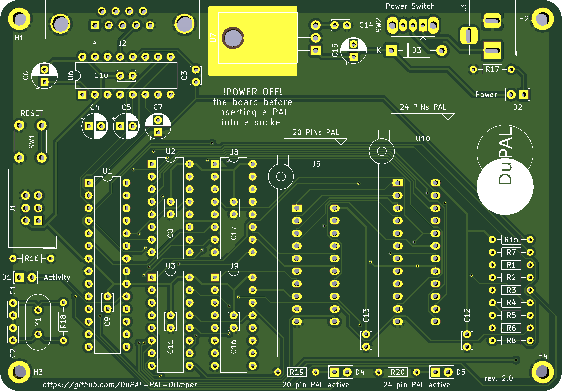
The DuPAL board is a simple circuit that mounts an AVR MCU (A classic ATmega328P of Arduino fame), three 74HC595 SIPO registers, one 74HCT166 PISO register, a MAX232 to adapt the serial port to RS232, a linear voltage regulator and a bunch of other passive components.
This board was designed and built to help myself bruteforce PAL devices. It has the hardware facilities necessary to scan all the inputs of the PAL, to check whether an output is high, low or hi-z and to report back the status to the host.
Details on how the features are implemented can be found on the Firmware's repository.
Software
Bootloader
This board uses the Optiboot Bootloader, currently at version 8.0, built for an ATMega328 running at 20Mhz, and with a baudrate of 57600bps.
The command line to build the bootloader is
make atmega328 AVR_FREQ=20000000L LED_START_FLASHES=8 BAUD_RATE=57600
See Compiling Optiboot for details.
The resulting bootloader can then be loaded via the ISP header. For example, by using avrdude and an AVR Dragon programmer:
avrdude  -c dragon_isp -P usb \
  -p atmega328p -e -u -U efuse:w:0xFD:m -U hfuse:w:0xDE:m \
  -U lfuse:w:0xFF:m -U flash:w:optiboot_atmega328.hex
Firmware
Details on the firmware can be found on the DuPAL_Firmware repository.
Hardware
The board was designed with KiCad EDA.
In its current form, the board is a pretty simple build, using exclusively through-hole components.
Powering the board
The board can be powered with a DC supply voltage between 7.5V and 9V, 12V is possible but the regulator starts to get hot.
The power connector has a positive tip, and is protected against reverse voltage by a 1N4001 diode.
Bill of Materials
- SW2 - Sliding SPST switch, pin spacing is 2mm, the outer 2 pins are just for mechanical stability
- J1 - 3x2 pins 2.54mm pcb male header
- C4, C5, C6 & C7 - 4x 1uF / 35v min electrolytic capacitors
- C15 - 1x 0.22uF / 35v min electrolytic capacitor
- C3, C8, C9, C10, C11, C12, C13, C14, C16, C17 - 10x 100nF ceramic bypass capacitors
- C1 & C2 - 2x 22pF NP0 ceramic capacitors
- R18 - 1x 1Mohm 1/4W resistor
- R17 - 1x 1.2k 1/4W resistor
- R16, R19 & R20 - 3x 680ohm 1/4W resistor
- R1, R2, R3, R4, R5, R6, R7, R8 & R15, 9x 10Kohm 1/4W resistors
- D1, D2, D4 & D5 - 4x 3mm LED (recommended red for power, green for activity)
- J3 - Power supply female barrel connector
- J2 - DB9 female angled connector
- SW1 - 4 pin push button
- D3 - 1N4001 diode
- U2, U3 & U9 - 3x 74HC595
- U8 - 1x 74HCT166
- U6 - MAX232
- U7 - 7805 TO220 regulator
- U1 - ATMega328p
- Y1 - 20Mhz HC49 crystal
- U5 - 20pin slim ZIF socket
- U10 - 24pin slim ZIF socket
- Heat sink for the power regulator (optional, but recommended)
- 5x 16pin socket (optional)
- 1x 28pin slim socket (optional)
Thanks @Porchy for the updated BOM.
