
 Per Mårtensson
39bf565723
Bugfix and add some files
Per Mårtensson
39bf565723
Bugfix and add some files
|
3 週間 前 | |
|---|---|---|
| .. | ||
| documentation | 1 年間 前 | |
| inc | 1 年間 前 | |
| .gitignore | 1 年間 前 | |
| LICENSE | 1 年間 前 | |
| Makefile | 1 年間 前 | |
| README.md | 11 ヶ月 前 | |
| make.bat | 1 年間 前 | |
| monroeoc8800diag.asm | 3 週間 前 | |
| monroeoc8800diag.bin | 3 週間 前 | |
| monroeoc8800diag.hex | 3 週間 前 | |
| os.mk | 1 年間 前 | |
| spt.md | 1 年間 前 | |
README.md
Monroe Diagnostic ROM
TRS-80 Diagnostic ROM
Model I with 4K:
Model III with 48K:
Model II with 128K:
Model 4P with 128K:
Main contributors:
- Dave Giller KI3V - Programmer and designer
- Frank IZ8DWF - Testing methodology and initial test routines
- Adrian Black - Testing, initial concept and QA
Introduction from Adrian
This project was born out of a broken TRS-80 Model III that I was working on. I could not tell if the system was even "executing code," so I used an early version of this ROM to help diagnose the problem.
Please know that the main goal of this ROM is to test the functionality of the video RAM (VRAM) and the dynamic RAM (DRAM, system memory.) It does not test any other component unrelated to those two subsystems. If a TRS-80 has good VRAM and DRAM, it should boot into basic where you can then run further tests.
You should familiarize yourself with the system schematics and design of the TRS-80 before using this ROM since problems in other areas of the system can sometimes manifest themselves of a RAM problem.
Videos:
- Model III Repair Part 1 and Part 2
- Model III, Diagnostic ROM Companion Video
- Model II, Diagnostic ROM test
- Model 1 Repair and VRAM upgrade Part 1 and Part 2
- Model 4P, Repair video Part 1, Part 2, Part 3 Coming soon.
In addition, most (all?) RAM tests contained inside the stock boot ROM and even disk/tape based tests use a very rudimentary RAM test that are inadequate to detect subtle RAM problems. While the test in this new diagnostic ROM isn't the end-all, be-all of RAM tests, we feel it is better than the typical simple bit pattern tests used elsewhere. The RAM test implemented here is a "march" test, which we have found to be much more reliable at detecting a variety of different RAM fault modes.
Feature List
- Working DRAM or VRAM is not required. The initial release of this ROM could use 8-bit VRAM for its stack, or use the first bank of DRAM as a stack if it tested good. This ROM now does not require a stack, and can run on a machine with faults in both VRAM and DRAM. For more information, see this explanation of the techniques used to operate in the absence of working RAM.
- Keep in mind however, that other faults, such as address line problems, can keep this (or any) ROM from running properly.
- One ROM image for TRS-80 Model I, or III
- Audio feedback via the cassette port, so you can tell what's happening even if you have no video display.
- Auto detection of VRAM type (The Model I comes with 7-bit VRAM)
- Auto detection of bank size (4k or 16k)
- A machine with 4K bank size cannot have RAM at 12K ($7000). If the ROM tests that region and finds all bits bad, it assumes this is a 4K machine.
- Officially, a machine with a 4K bank can only have 4K total, so this ROM does not test beyond the first bank in that case.
- Testing up to 48k of DRAM, looping continually.
- One ROM image for TRS-80 Model II with all DRAM sizes.
- The same image is expected to work with the Model 12, 16, 16B or 6000, although this is not tested.
- Testing full 2K of VRAM
- Testing up to 512K of DRAM, looping continually.
- Temporarily relocates the test subroutine into previously tested RAM at
$4000and unmaps the ROM from Z80 address space to test the RAM between$0000and$3FFF.- The stock BOOT ROM does not test the region of DRAM from
$0000-$0FFFthat is hidden while the ROM is mapped. It also does not test any RAM above 32k -- so any faults in the untested parts of RAM will go undetected. This ROM tests 100% of the DRAM.
- The stock BOOT ROM does not test the region of DRAM from
- This version of the ROM has preliminary support for booting to floppy or hard drive (incluyding FreHD48). There are known issues with booting at this time, and the symptoms vary between the Model II, 12, 16, 16B, and 6000.
- One ROM image for TRS-80 Model 4P with 64K or 128K.
- This is an early version that tests all RAM except the lowest 16K.
- Testing the lowest 16K will require a relocating test similar to what is done for the Model II tests, but this is not yet implemented.
- If the machine has 128K, the upper bank if tested in two halves.
- This ROM has only been tested on the model 4P, but is expected to work on the model 4 and 4D as well (all GA and NGA models).
- This is an early version that tests all RAM except the lowest 16K.
- All ROM images fit within 2K so the ROM can be used on any machine in the range using a normal 2716 EPROM.
Future improvements
- Testing the ROM on "Big Tandy" systems like the Model 12, 16, and 6000.
- Testing on the Model 4 and 4D
- Porting the diagnostic routines to other Z80 systems
- Kaypro II'83, 4'83, 10, 2'84, 4'84, 1
- More comprehensive documentation
What the ROM does
- Makes sounds to let you know the ROM is running even if the display is not operating properly:
- On the Model 1/III:
- Makes a beep from the cassette port (so you can know the system is executing the ROM.)
- On the Model 4P:
- Makes a beep from the internal speaker.
- On the Model II:
- Accesses the built-in floppy drive three times. The activity light should activate and the head solenoid should click. (See Model II video above to see this in operation.)
- On the Model 1/III:
- Set the system to 64 or 80 column mode depending on the machine.
- On the Model 4P, displays a test pattern in 80 column mode for a visual test of the VRAM as well as a test of the 80-column hardware. Then switches to 64-column mode for the rest of the tests, including the March VRAM test.
- Tests the video RAM using a March C test.
- On the Model I/III:
- Tests for 7-bit Model I VRAM (fake bit 6) and identifies it if found.
- On the Model I/III/4P:
- Beeps a good (rising tones) or bad (tune ending on low note) VRAM sound.
- If the VRAM is bad, it will show a test pattern on the screen, then beep out which bit(s) are bad repeatedly.
- On the Model II:
- If the VRAM is bad, it will show a test pattern on the screen, then blink the drive light on floppy 0
- The bits of VRAM are indicated by long or short blinks, counting from bit 7 down to bit 0.
- A long blink means that bit is bad. A short blink means that bit is good.
- The bits of VRAM are indicated by long or short blinks, counting from bit 7 down to bit 0.
- If the VRAM is bad, it will show a test pattern on the screen, then blink the drive light on floppy 0
- On the Model I/III:
- Clears screen and writes a welcome message.
- On the Model I/III:
- If the first bank of DRAM only has 4K:
- Tests that first bank of 4k repeatedly. These systems cannot have more than 4K of RAM, so nothing above 4K is tested.
- If the first bank of DRAM is 16k:
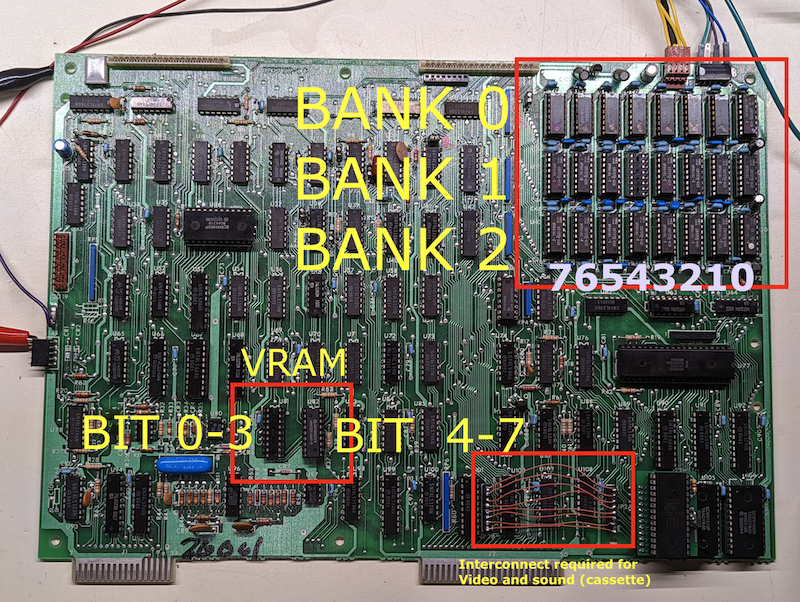
- Tests all three DRAM banks (48K) repeatedly. Missing banks (e.g., for a 16K or 32K machine) will be listed with all bits in error (
76543210).
- Tests all three DRAM banks (48K) repeatedly. Missing banks (e.g., for a 16K or 32K machine) will be listed with all bits in error (
- If the first bank of DRAM only has 4K:
- On the Model I/III/4P:
- After each test, the diagnostic will play a good bank or bad bank tune. If a bad bank exists, it will beep out which bits are bad and print this to screen.
- It is possible to run the diagnostic ROM with NO DRAM installed at all. It will still work properly.
- The Model II can (theoretically) have up to 512K of DRAM:
- The first 32K of DRAM (from
$0000to$7FFF) is always present, but at boot time, the ROM is mapped in and makes the RAM from$0000to$0FFFinaccessible.- The diagnostic first tests the second physical bank of DRAM located at
$4000-$7FFF.
- If that bank passes testing, the ROM copies a portion of itself to
$4000, and passes control to this copy.- The relocated copy unmaps the ROM, exposing all of RAM from
$0000to$3FFF, which it then tests. Afterwards, it re-maps the ROM to appear at$0000again, and hands control back to the ROM.
- The relocated copy unmaps the ROM, exposing all of RAM from
- If the bank at
$4000-$7FFFfails testing, the ROM skips the test of DRAM from$0000to$3FFF.
- If that bank passes testing, the ROM copies a portion of itself to
- Then the diagnostic tests all possible DRAM pages (
$0-$F), bank-switching them in turn into the region$8000-$FFFF. - It is possible to run the diagnostic with NO DRAM installed at all. It will still work properly.
- The diagnostic first tests the second physical bank of DRAM located at
- The first 32K of DRAM (from
Running this diagnostic ROM on a TRS-80 Model I or Model III
The Diagnostic ROM is less than 2K in size, so it will fit completely within a 2716.
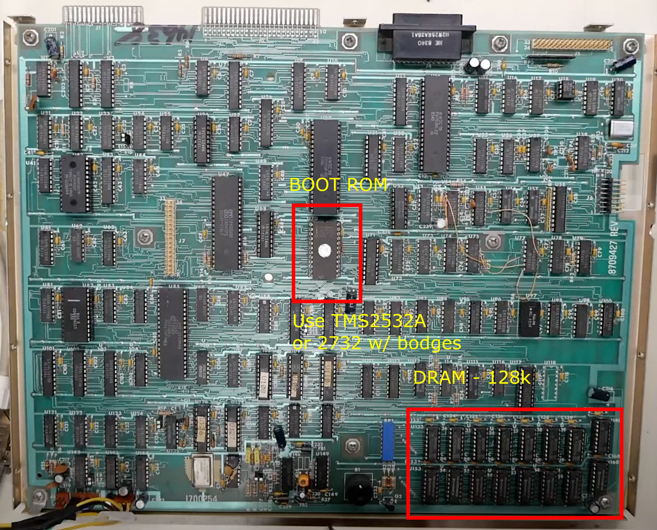
To use this diagnostic ROM on a TRS-80 Model III, you must first make or buy an adapter to allow use of an EPROM in the U104 ROM socket. This socket is designed for a 2364 which does not have a compatible pinout with a 2764 EPROM. Adapter PCBs are widely available on the usual sources, or you can make some PCBs at this link:
PCBway Project Link for EPROM adapter
The assembled ROM, ready to be burned to EPROM or EEPROM, is trs80testrom.bin or trs80testrom.hex. Both contain the same ROM image, so you can use whichever is more convenient with your EPROM programmer's software.
One you have a programmed 2764 or 28B64C, insert that into the adapter and install it into U104 on the Model III. This is the boot ROM that the CPU starts to execute code from at power-up. (Address $0000)
On a TRS-80 Model I, you can install the 2716 chip right into the motherboard in left-most socket. This is the same socket the Level II ROM expansion ribbon cable connects to and is the method we recommend you use.
You can also install the ROM into the Level II ROM upgrade board on the keyboard side, but the layout of these ROM chips can vary depending on revision of the upgrade. You must install the 2364 adapter or possibly a 2732 into the socket containing the primary boot ROM. If using the 2364 to 2764 adapter in this socket, you will need to load the ROM image into $1000 due to one address line being tied to VCC.
- The beep codes for bit errors are as follows:
- First a long middle tone is played:
- A single tone for the first bank, two for the second, and three for the third
- Then after a short pause, the good/bad bits are identified:
- If all bits are good, a long high tone is played.
- If all bits are bad, a long low tone is played.
- If some bits are good and some bad, the bits are identified starting with bit 7 and counting down to bit 0:
- A short high tone indicates this bit is good.
- A short low tone indicates this bit is bad.
- First a long middle tone is played:
- For example, if your second 16K bank (locations
$8000-$BFFF) have bits 5 and 3 bad, the following tones will play:- MID(long) MID(long) (pause) HI HI low HI low HI HI HI
- If only bit 6 of VRAM is bad, the diagnostic will further test to see if bit 6 is "faked" as the NOR of bits 5 and 7.
- If it is, you will not hear a beep code because the ROM identifies this as the normal 7-bit VRAM in a stock Model I machine.
- If bit 6 of VRAM is not consistently the NOR of bits 5 and 7, the screen will be filled with copies of the character set, and the error will be repeatedly reported as tones (HI low HI HI HI HI HI HI, identifying bad bit 6).
Running this diagnostic ROM on a TRS-80 Model II
WARNING: You use this ROM (or really, do any troubleshooting inside a Model II or its derivatives) at your own risk!
The CRT on the Model II (and all of the "Big Tandy" machines that use a 6845 CRT Controller chip) and could be damaged if they are powered on and run without a valid signal from the video controller board. It is very important that you are careful to connect all of the video-related cables properly. Also, while we have tested this ROM to program the CRTC correctly, if your EPROM chip is not programmed successfully or not inserted into the ROM socket correctly such that no ROM code runs, the video board will not output any video signal. Even if you are sure everything has been prepared correctly, make sure you are ready to cut power if you hear strange sounds from the CRT or anything doesn't seem right. We've been warned that the technical documentation says you have roughly 3 seconds to cut power before there is risk of damage to the CRT. We don't know if that's true, but we don't want anyone to damage their machine, so if you proceed, do so with caution.
Do note: this code currently depends on proper operation of the FDC. Specifically it awaits proper responses from the FDC while it toggles the activity light and head loading solenoid on and off. In the near future this will be modified to wait appropriate time periods, but not to rely on the data read from the locations where the FDC status registers should be. During testing, even without the FDC installed, the diagnostics ran properly, likely due to the response bit being 0 when read back even with the controller removed. It may not work this way on all systems, as the data bus will be floating during this read operation and results can be erratic.
The ROM image fits into a 2716, so it is easiest to use one and install that into the single ROM socket on the CPU board. Alternatively, you can use the 2364 to 2764 adapter mentioned above, but as with the TRS-80 Model 1, you must load the ROM into $1000 when programming.
As soon as you power on the machine, you should hear the floppy drive clicking, even before the CRT warms up, so you know the diagnostic code is running.
This version of the ROM has preliminary support for booting to floppy or hard drive (incluyding FreHD48). There are known issues with booting at this time, and the symptoms vary between the Model II, 12, 16, 16B, and 6000. To ensure that this ROM loops the RAM tests indefinitely instead of attempting to boot your system, make sure there is no bootable floppy in drive 0, and make sure any hard drive (or HD emulator) is disconnected or powered off before running this ROM.
This section to be completed.
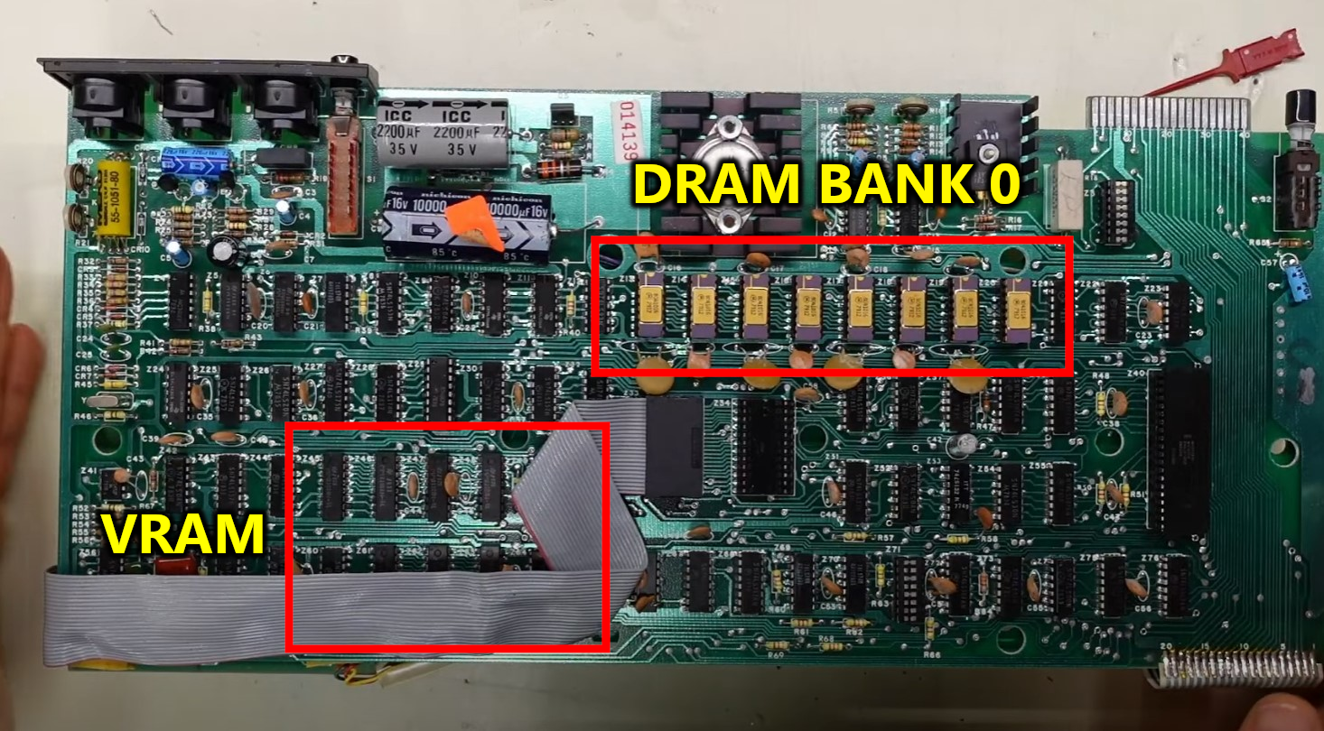
Running this diagnostic ROM on a TRS-80 Model 4/4P
Note: The ROM has only been tested on a 4P. It should work on the 4/4D, but YMMV.
On the 4P, the stock boot ROM is just a 2332, so you can use a TMS-2532A to replace it, or use a 2732 EPROM but you have to swap around the top address line and also ground the output enable pin. (The 2332 doesn't have this pin, so the motherboard holds that pin at 5V.)
Flash the test ROM code into the EPROM and install into the motherboard. You should hear a start-up been and then, if the RAM test is running, you will hear beeps indicated the testing of each part of RAM.
You can actually run the TRS-80 Model 1/III ROM in the Model 4P, and it does work. It will only test 64 column mode and only test 48k of DRAM, but if you have problem with the system running in 80 column mode, this may be a good test to see how well the system is running.
Other troubleshooting notes
- On the Model III, you must have a working connection between JP2A and JP2B to run this diagnostic. Both the cassette port (for audio output) and the video subsystem is accessed by the CPU via this interconnect. Bits 0 and 1 of this interconnection are needed for the cassette port audio, but all 8 bits are required for video to work.
- You do not need the interconnect between JP1A and JP1B. This is used by only the floppy and serial board. The system will operate fine without the interconnect, but you will not be able to use the floppy or serial port.
- On the Model III, the cassette port output is the pin closest to the keyboard connector (Connector J3). On the Model I, you can either clip a test lead onto the cassette port, or use the cassette DIN cable to get audio output.
- You do not need any DRAM installed in the machine for the diagnostic to run. If you have good working VRAM but no working DRAM, you should see the DRAM tests run, and all banks will come back as bad.
- Keep in mind a stuck or bad DRAM bus transceiver can trash the entire bus, causing the VRAM test to also fail.
- You do not need the keyboard connected for the system to run the diagnostic. The keyboard is not used during the test at all.
- The diagnostic ROM must be installed into U104 on the TRS-80 Model III. You must use a 2364 to 27XXX adapter. The one Adrian used is made for 27128 devices, but it works just fine with 2764 and more conveniently 28B64C (EEPROMs.)
- You can also use this same adapter in U105 (for testing replacement of that ROM, not for running this diagnostic ROM). You can use a normal 2716 in U106 if you need to test replacing that ROM.
- You do not need to have any ROM installed in U105 or U106 during the test, as they are not used by the diagnostics. A bad ROM in one of those sockets could cause the computer to not work, so if even this diagnostic ROM does not work, it would be advisable to try pulling those ROMs.
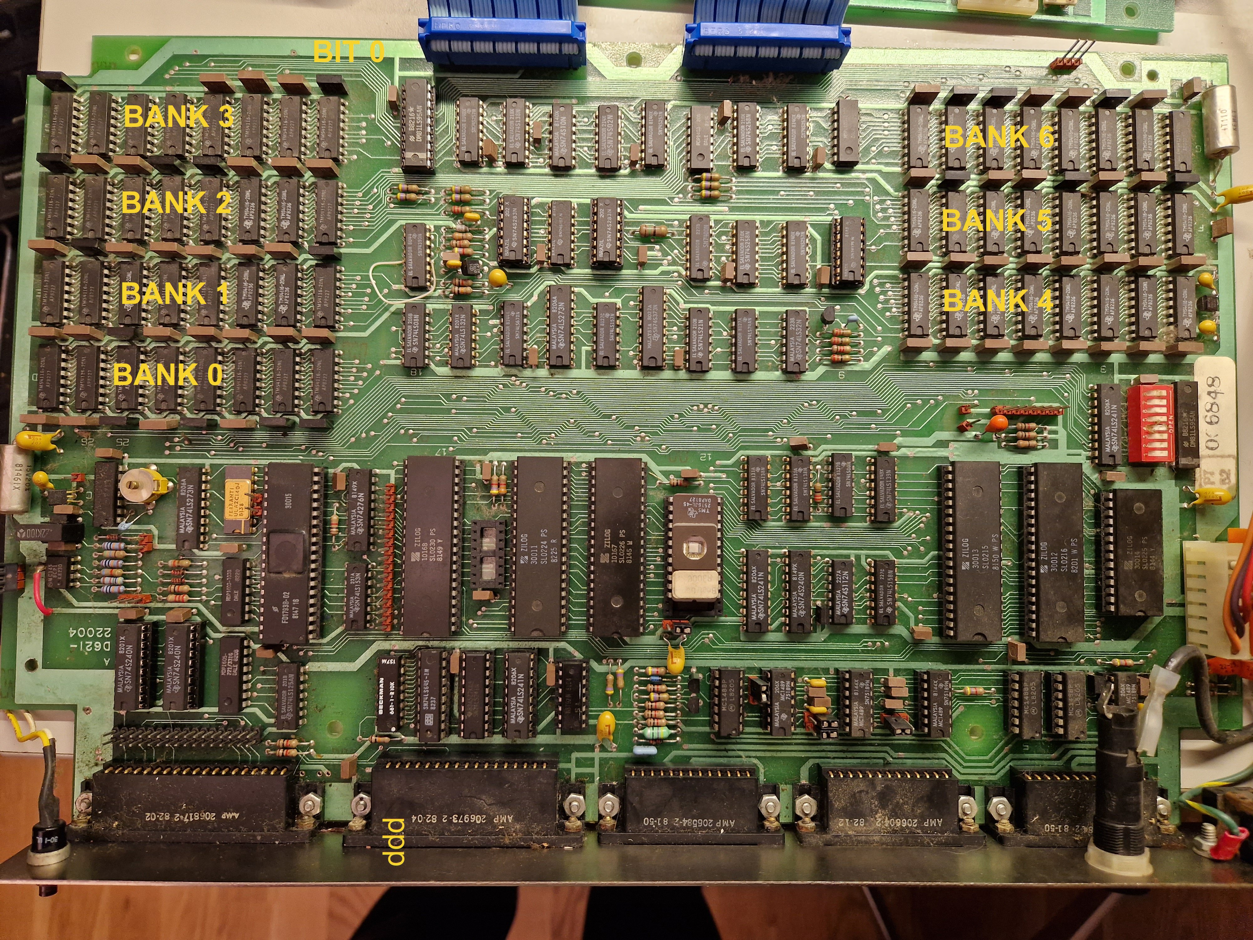
Knowing what might be wrong
The Model III motherboard layout is shown above. I recommend referring to the Radio Shack Technical Service Manual for help in identifying what components might be bad on your system, but the picture should give you a head-start.
The Model I motherboard has only 1 bank of DRAM, which can 4k or 16k. If the system has 16k, then an additional 32k can be installed in an attached expansion interface.
For the ROM position in the Level II PCB, you must figure out which ROM is the lower ROM. You may have to look up part numbers of the chips to figure that out.
The Model 4P motherboard has a 2332 bootrom, you need to use an adapter or a TMS2532A in this socker. If you have neither, you can use a 2732 EPROM but you must swap around a couple pins and ground hte /OE pin on the EPROM. (See pin outs of these chips to understand.)
The RAM test on the 4/4P is not complete due to the way the banking works -- but it will FULLY test the upper 64k of RAM, so you can swap the lower bank chips with the upper bank to get a full test.
Building
This repository will contain the assembled ROM image. To assemble, you will need to use George Phillips' zmac assembler.
Many thanks to George also for his excellent trs80gp emulator which includes integrated debugging facilities which dramatically reduced the time necessary to develop and debug these diagnostics.